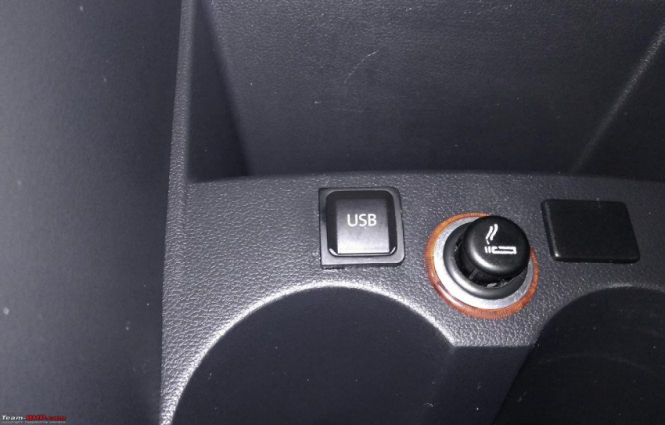
If you can source the OE USB port and the cable, you can even have the port installed in front of the gear lever.
BHPian Gannu_1 recently shared this with other enthusiasts.
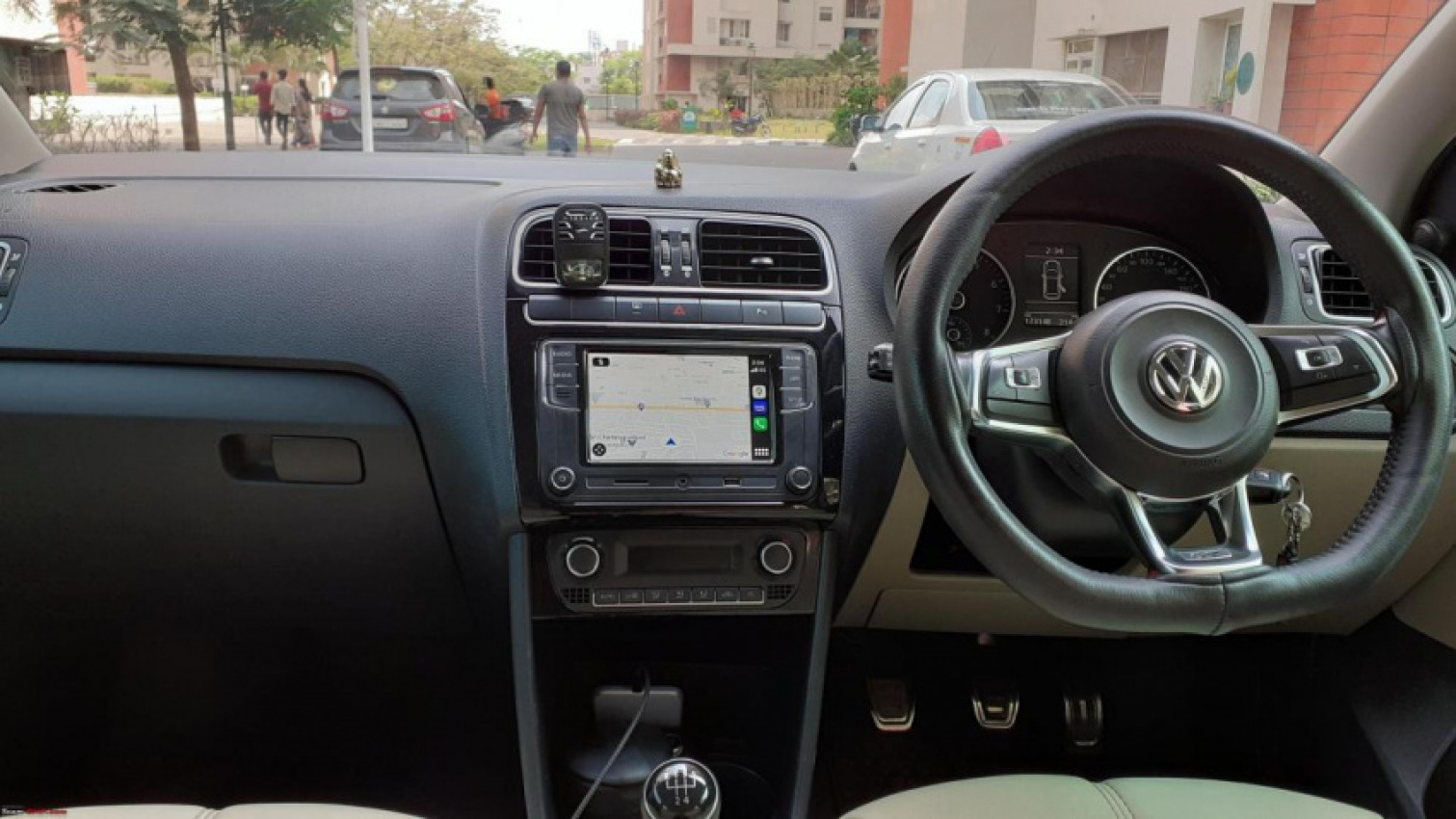
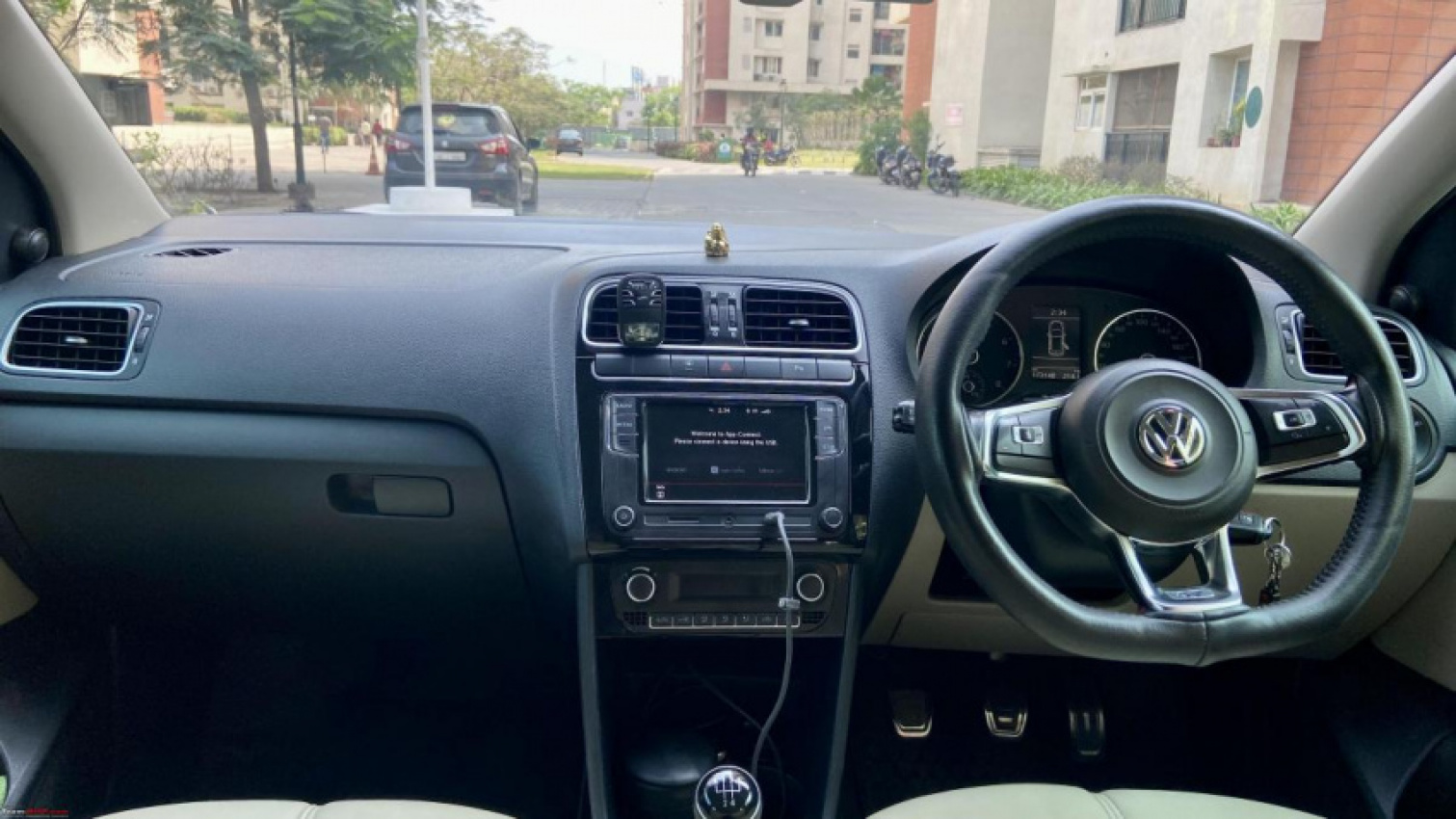
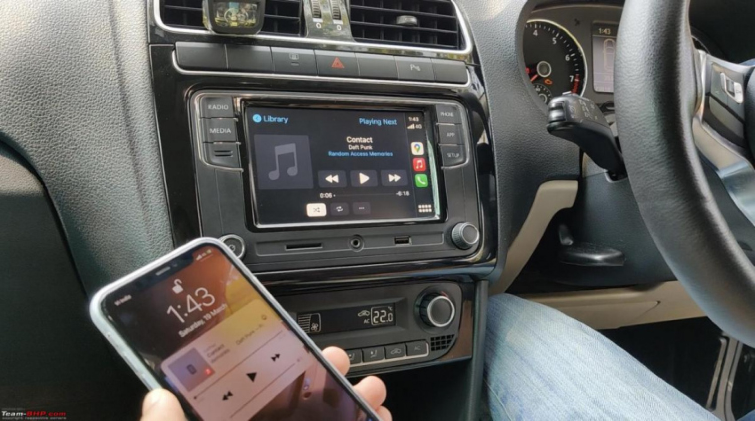
The RCD 330, 340 series head units have a USB port at the front. Android Auto and Apple CarPlay users would connect their smartphones to this front USB port. But the USB cable connected to the unit is an eyesore especially if you have the entire cable dangling this way:
There is a workaround for this – solder a USB terminal to the same port on the PCB, lead it to the rear of the unit and connect the USB/Lightning cable to your smartphone. That way the cable is hidden and the dashboard looks a lot cleaner:
If you can source the OE USB port and the cable, you can even have the port installed in front of the gear lever like this:
Parts required
- Micro USB cable – A charging cable bundled with a device like Amazon Echo. Don’t rely on 4 or 5 thin bare cables as they may not work due to the lack of braided shielding which reduces noise and EMI.
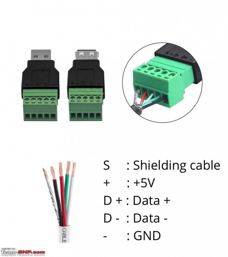
- Female USB A screw terminal – You can get these locally from electronic spares shops. The terminals are numbered and you have to strip the insulation of the cables and screw it down.
Tools required
- Torx T8 bit/screwdriver – To remove all the Torx screws from the head unit.
- Mini Phillips screwdriver – For the screw terminal unit.
- Soldering iron – For soldering the cables to the board’s terminals. A pointed bit will be helpful.
- Soldering iron stand.
- Wire cutter and stripper.
- Hot glue gun – To pour hot glue over the soldered terminals to prevent wire movement and dislodging later.
- Heat gun (optional) – To melt the hot glue poured over the soldered terminal so as to melt the glue evenly. If you can achieve this with the glue gun itself, you don’t need a heat gun.
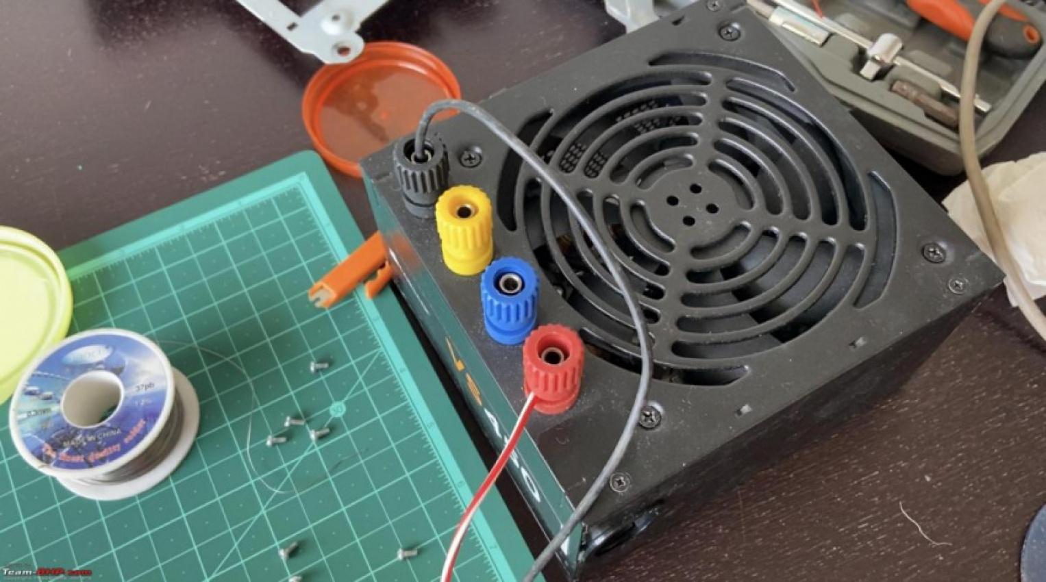
- Bench power supply – To test the functionality at home before installing it in the car.
Consumables required
- Solder lead
- Soldering flux
- Cable tie
- Glue stick
Procedure
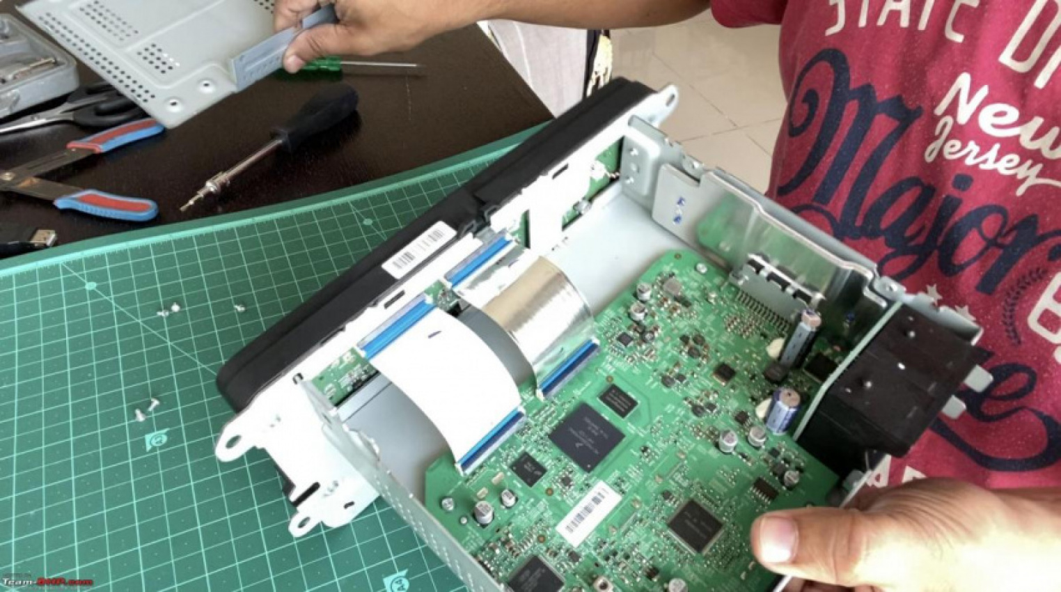
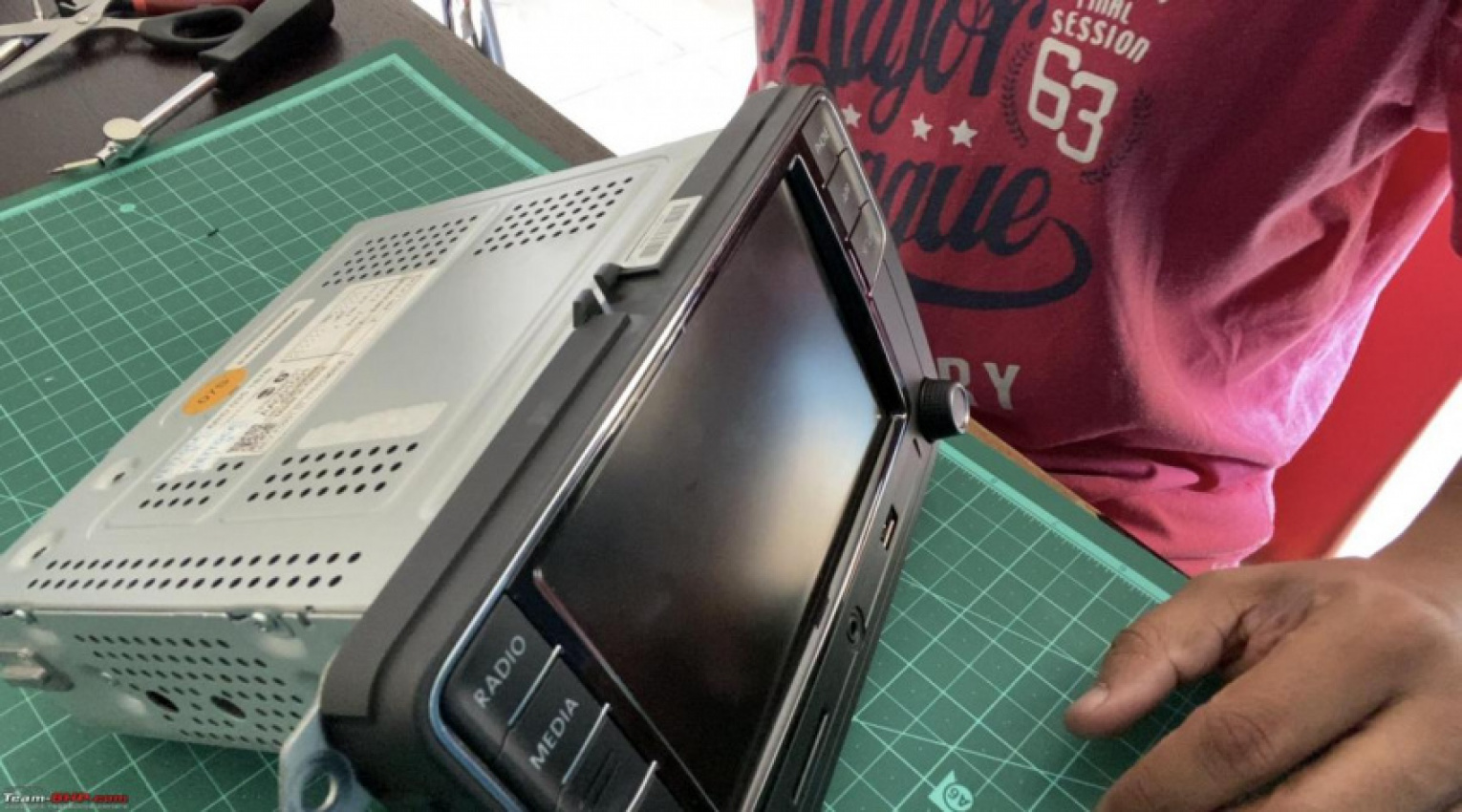
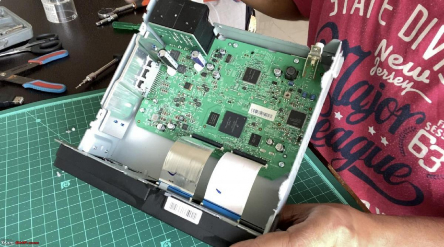
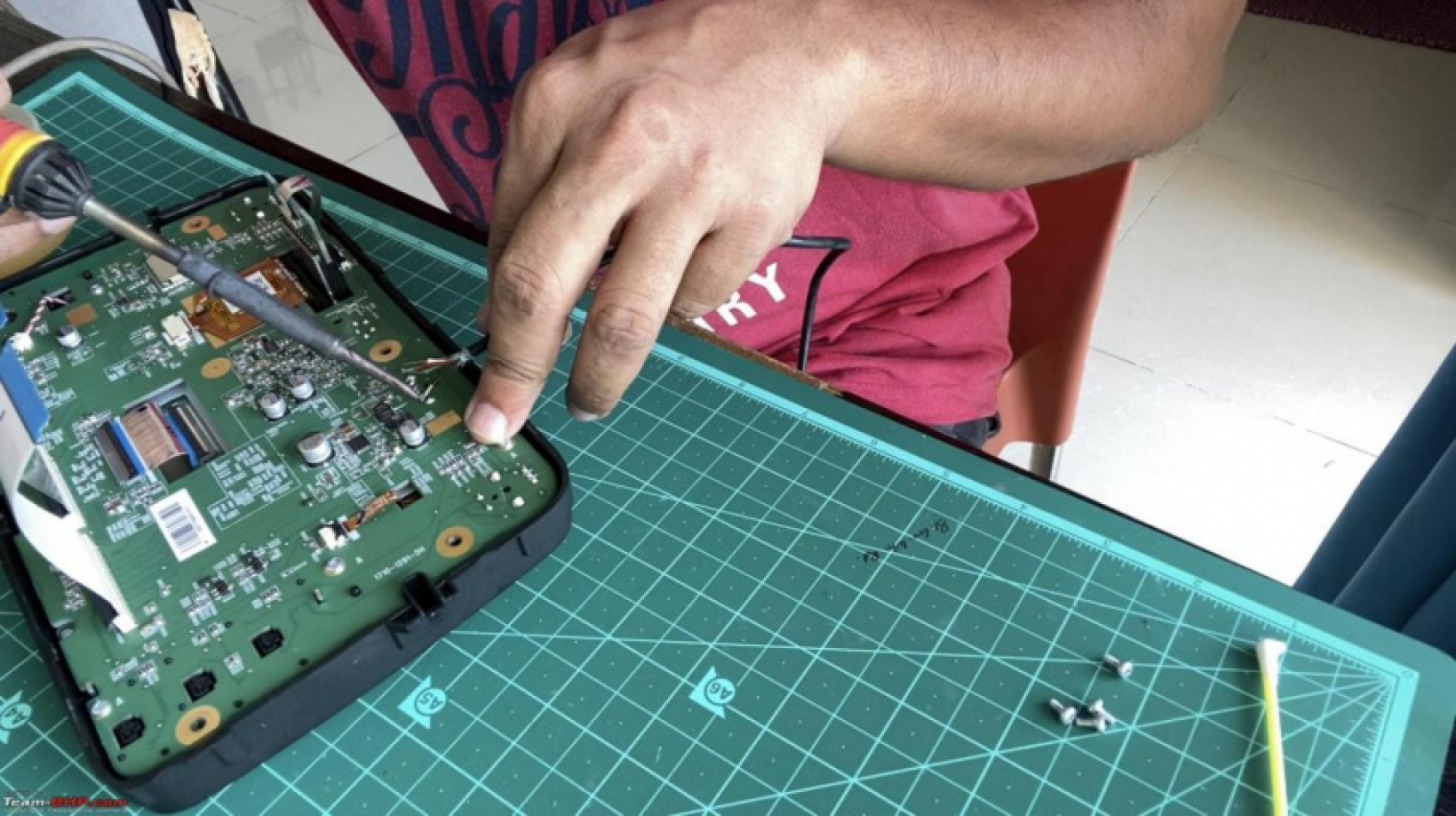
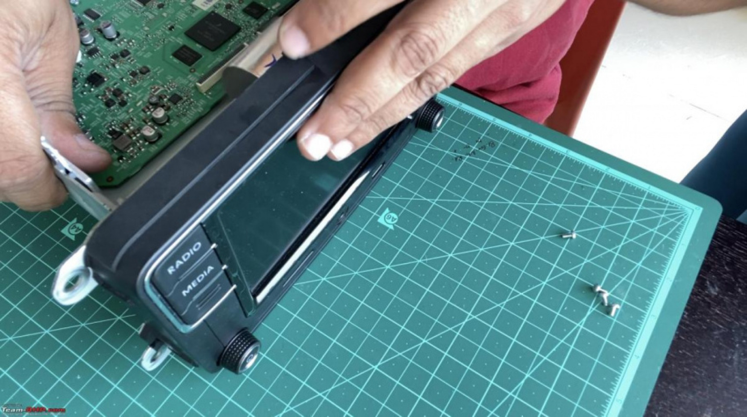
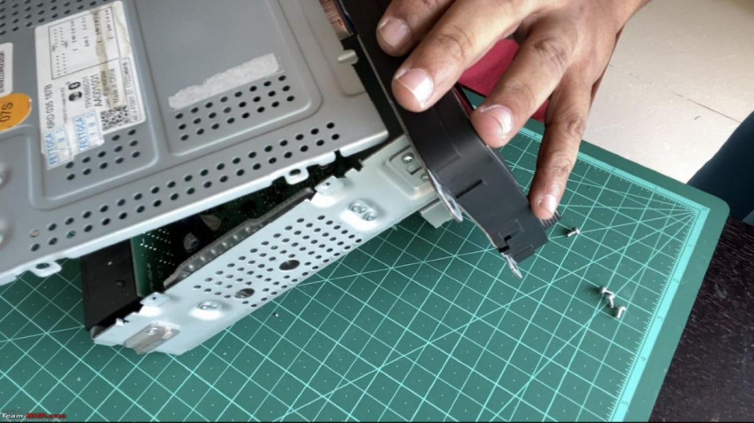
Remove the head unit from the car and take it to your bench:
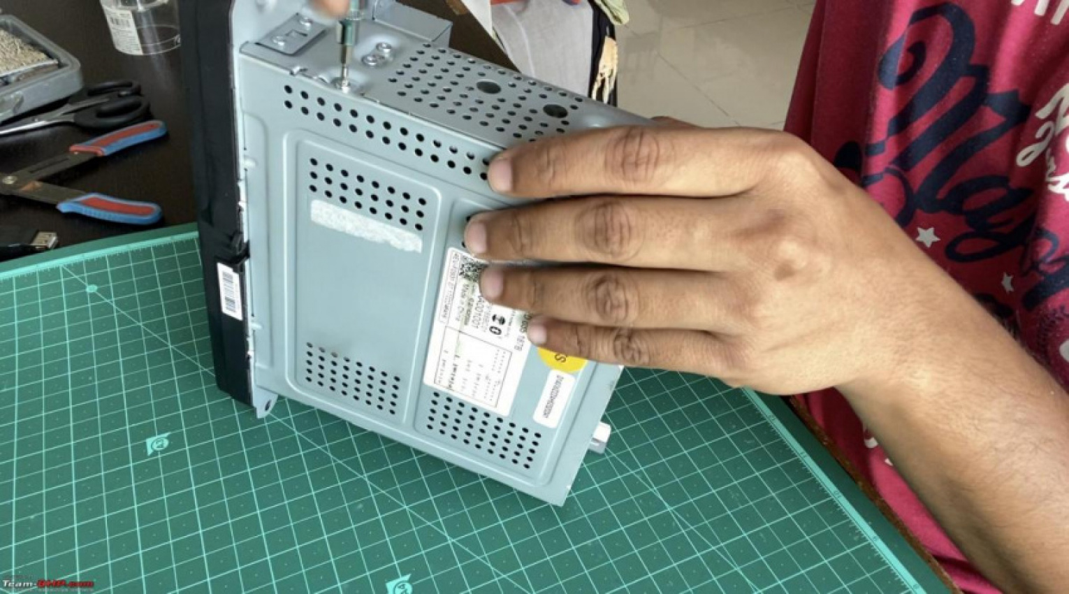
Using the T8 Torx bit, remove the Torx screws holding the top plate. There are 7 screws – 2 on each side and 3 at the rear.
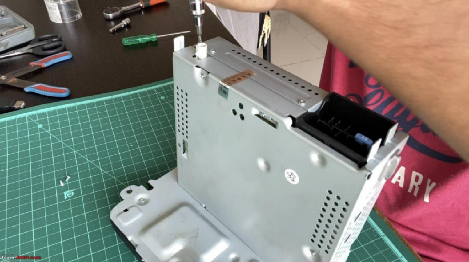
Remove the top plate
Since there are several variants of the RCD 330 and 340 manufactured by different OEMs, this may vary depending on the unit you have.
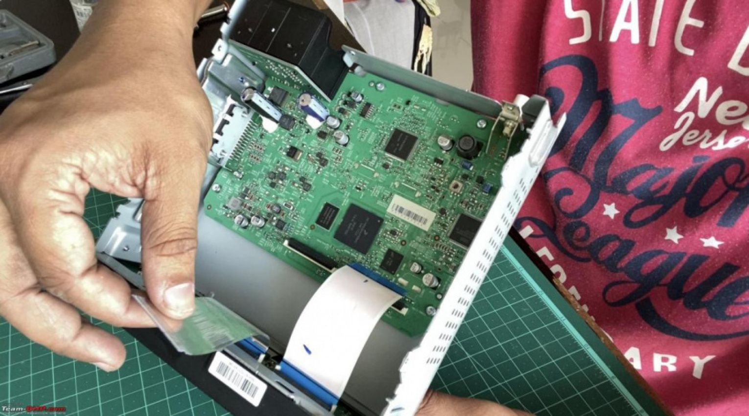
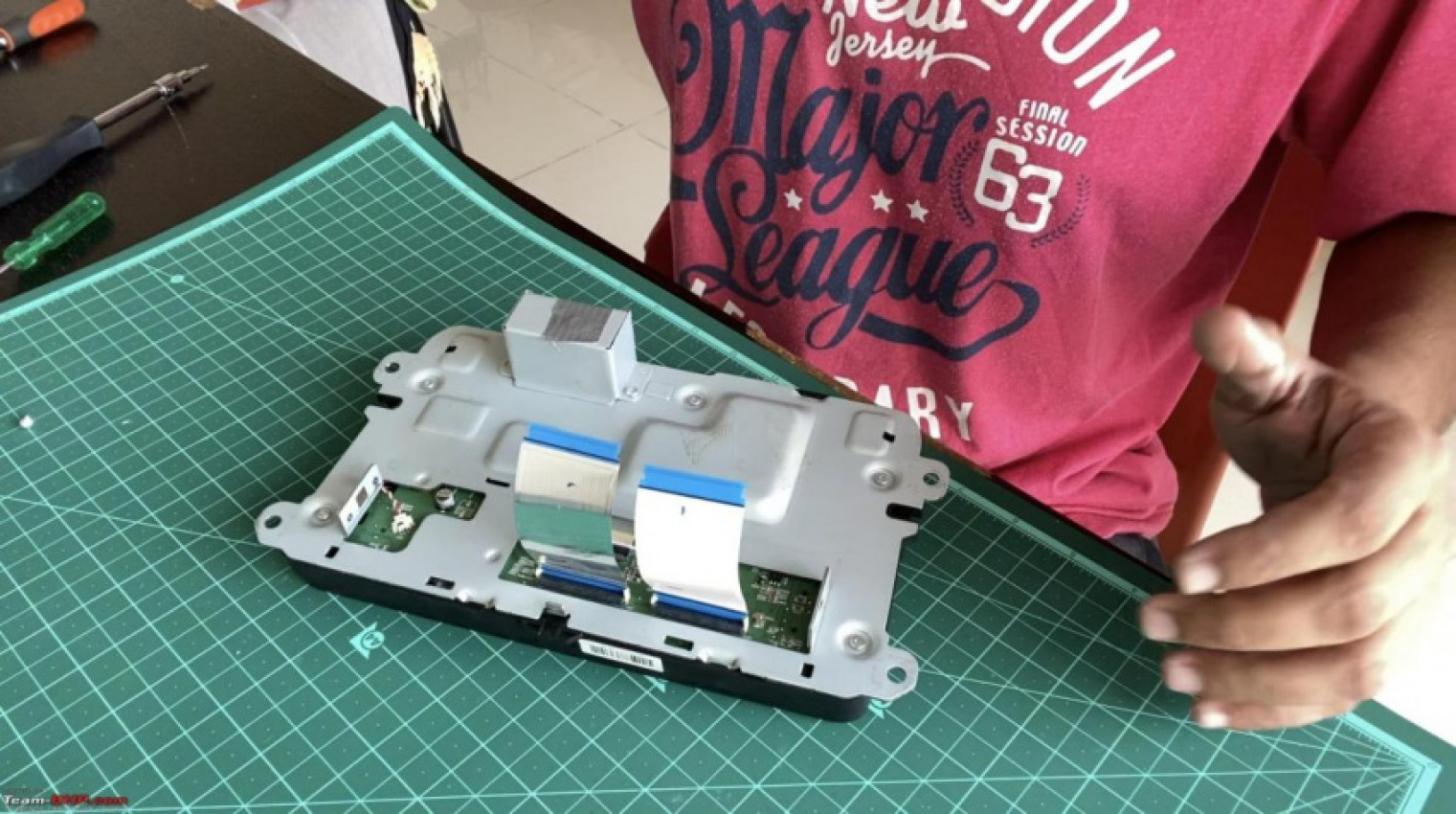
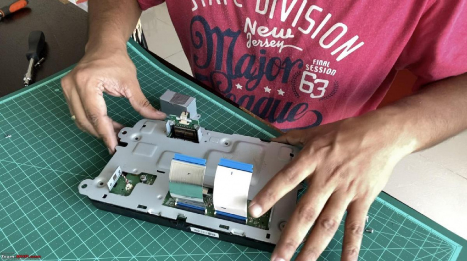
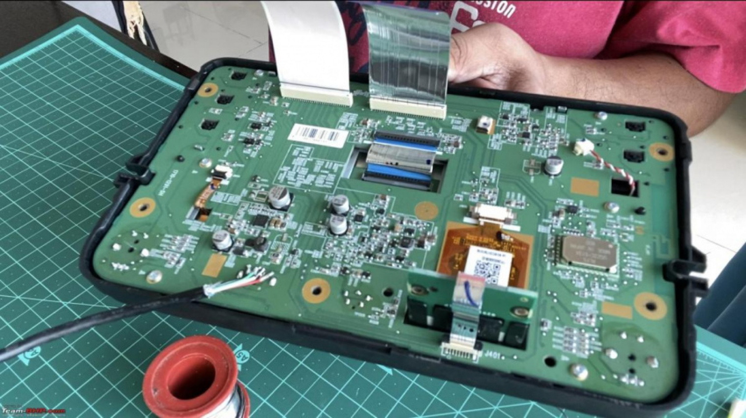
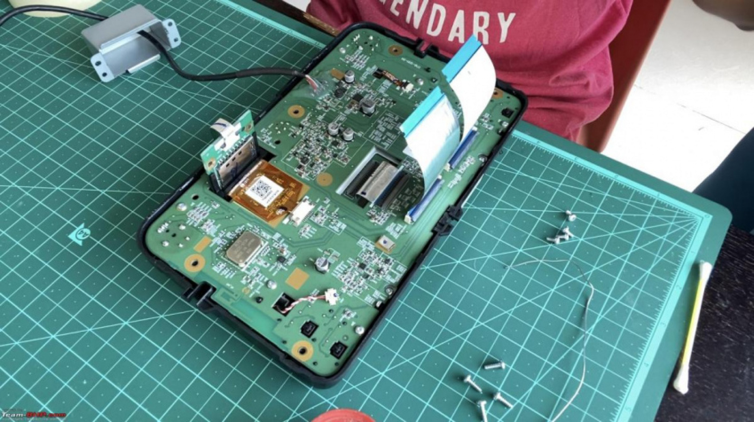
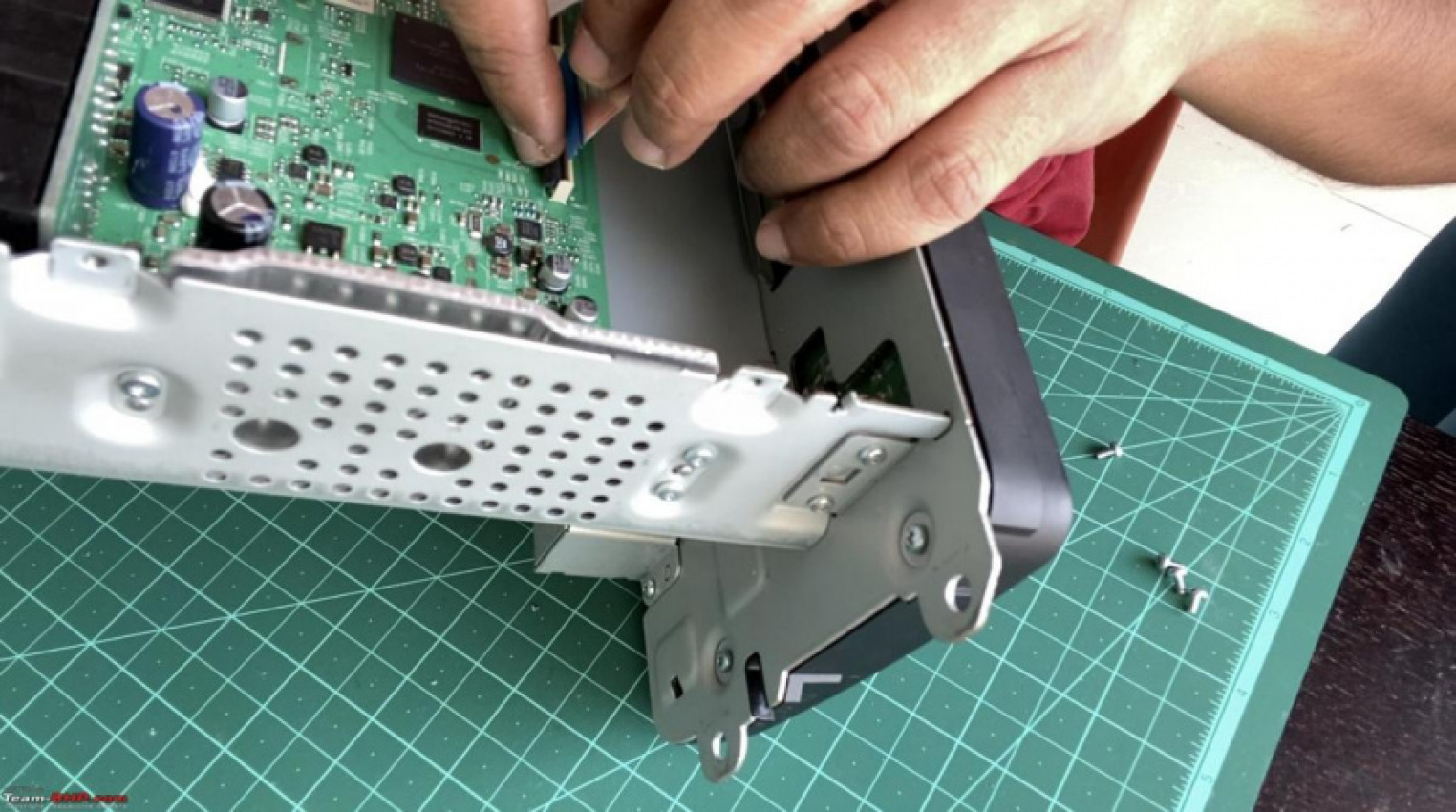
Once the top plate is removed, you have to detach the LCD unit from the main unit. For this, you need to remove the 2 flat ribbon cables connecting the motherboard to the LCD board.
Push the tab on the ribbon connectors to the top and gently detach the ribbon cables.
The LCD unit is screwed to the main body with 2 screws on each side.
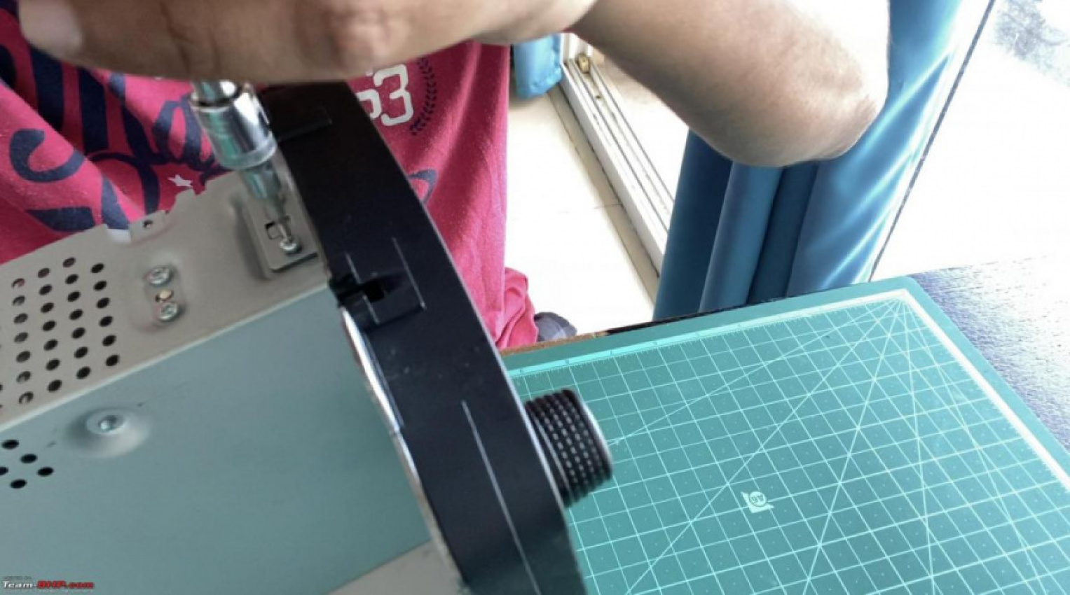
Undo the screws and gently separate the LCD unit from the main body.
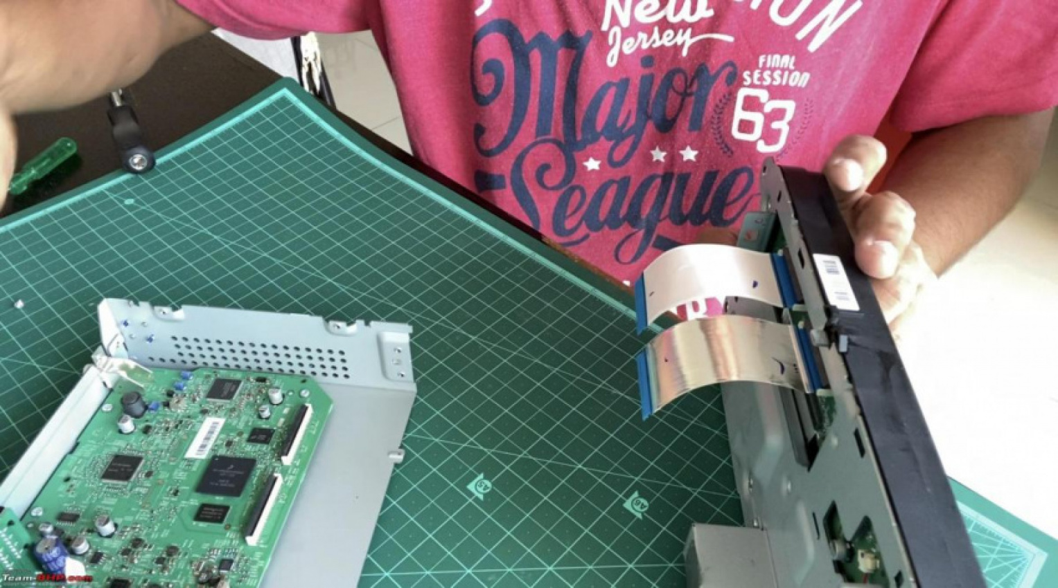
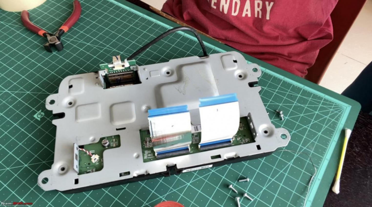
Remove the metal backplate from the LCD unit. 5 Torx screws hold the back plate to the main board:
Undo the 2 screws and detach the SD card board’s metal enclosure:
And lastly, 2 screws holding the back plate with the SD card board:
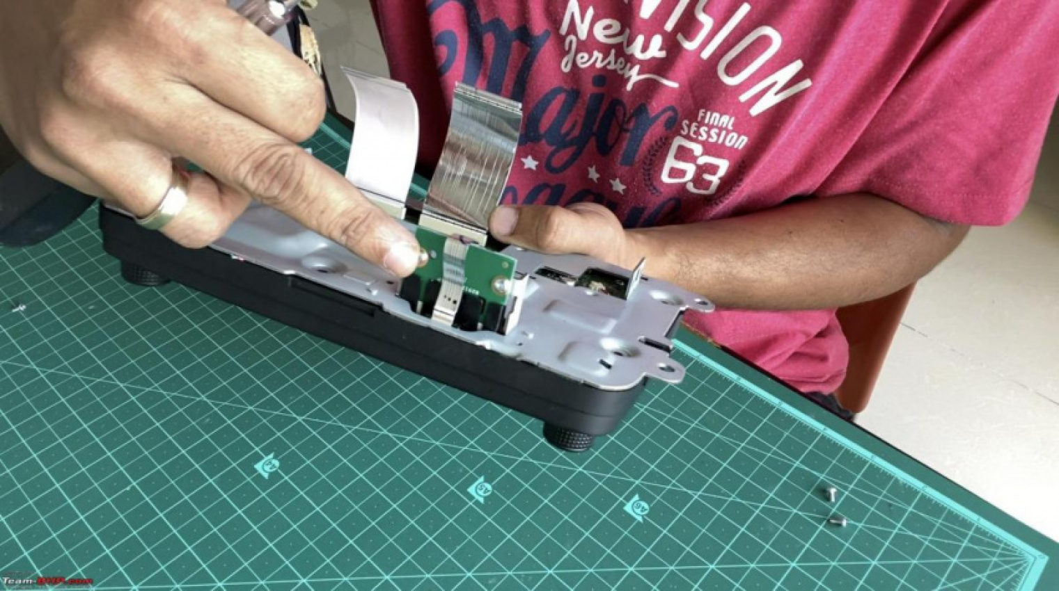
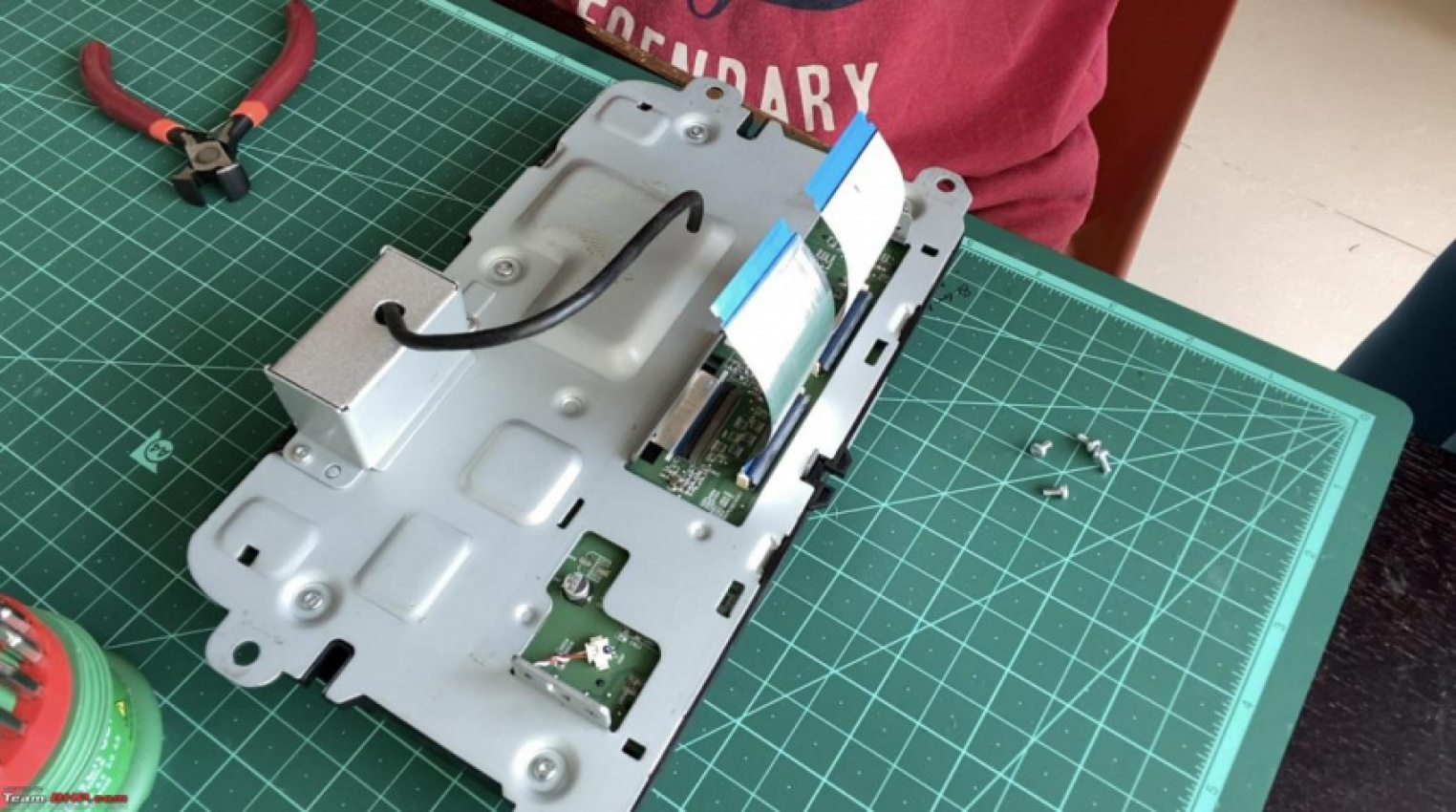
Gently pry open the metal enclosure from the LCD unit:
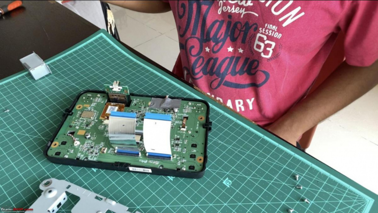
By now you’ve removed about 20 screws. Keep all the screws safe and segregated based on their size (there are only 2 sizes going by my experience).
Cut the 2 ends of the micro USB cable, shorten the length of the cable based on your requirement and strip the insulation of the 4 cables at both ends.
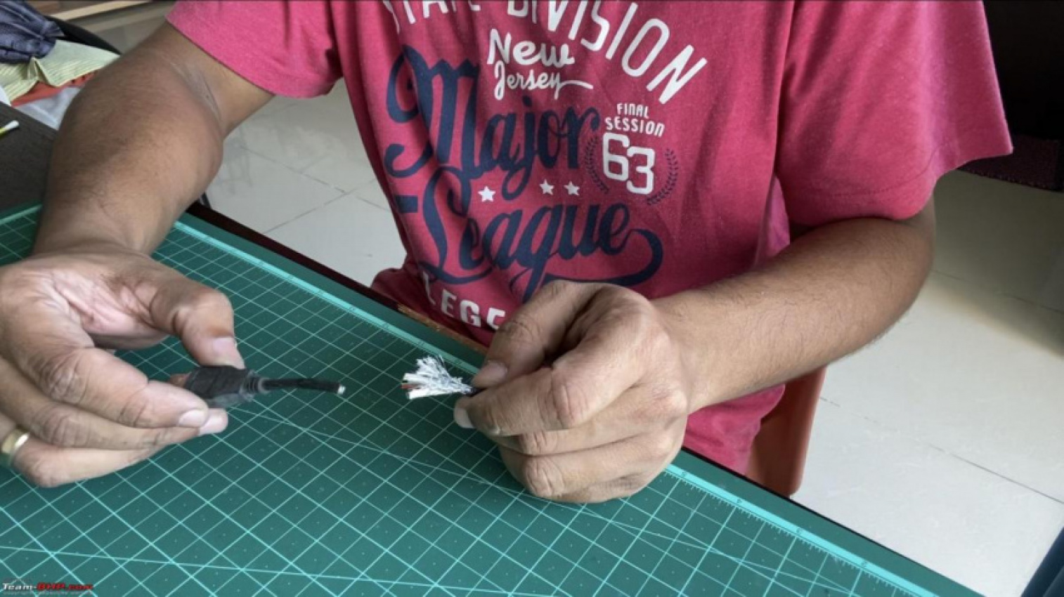
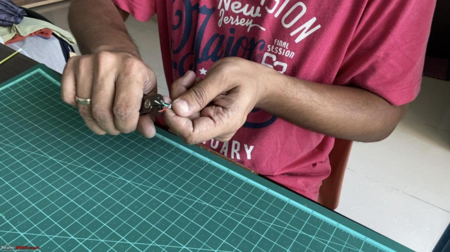
A good quality USB cable will have a braided shielding around the 4 cables which acts as a shield to cut down the electrical noise and EMI. The cables will be usually color coded red, white, green and black.
- Red – +5V
- White – Data –
- Green – Data +
- Black – GND
This is the rear of the USB port soldered to the LCD board:
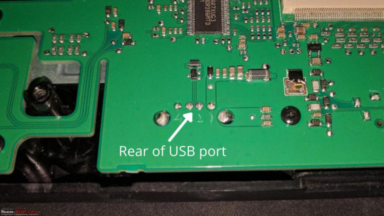
They are numbered this way:
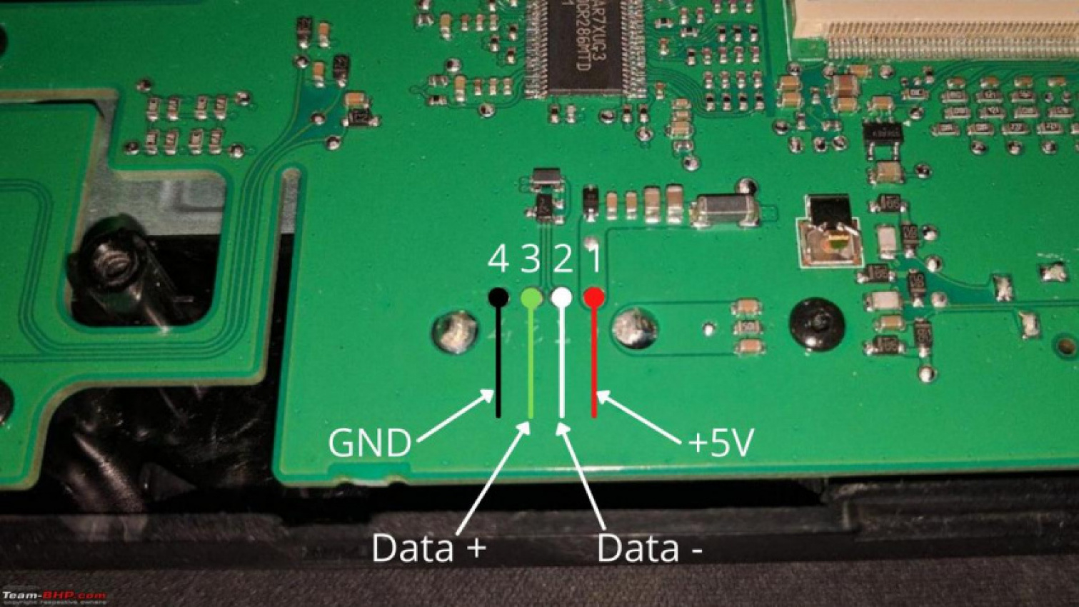
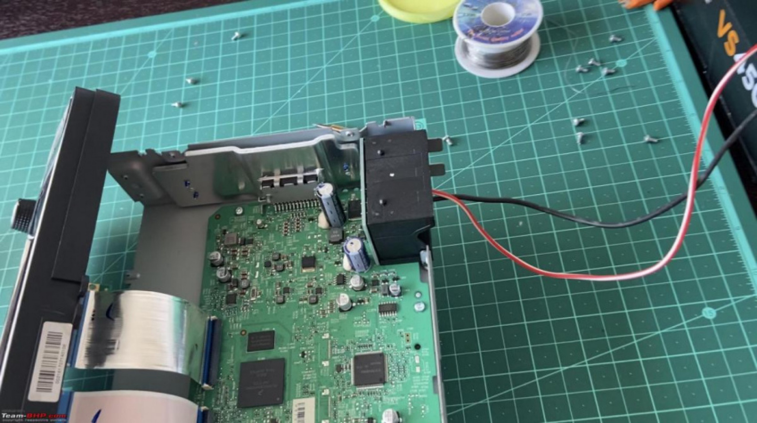
Solder the leads of the USB cable to the port:
This was incredibly hard for me because the solder would just not stick to the cables and the heat from the soldering iron would melt the thin insulation over the cables! Took a few tries and the end result wasn’t the best but it passed my test.
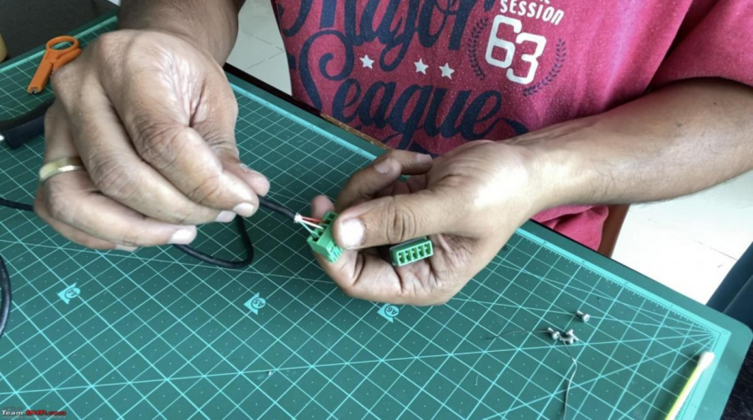
The other end is connected to the female USB A screw terminal:

The terminal is numbered this way:
Connect the leads and screw them down properly:
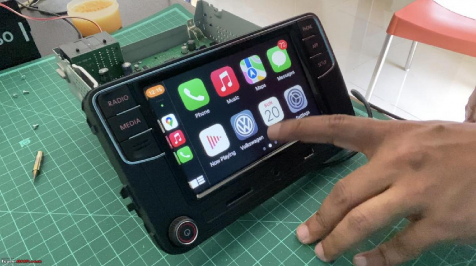
After the USB cable is connected, do a quick bench test to check if it is working as it should (Android Auto/CarPlay):
After confirming that the modification is working, add some hot melt glue over the soldered joint to prevent the wire(s) getting dislodged from the board due to the cable movement or pulling:
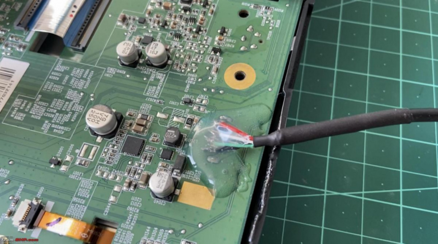
Optional: Use a heat gun to spread the glue evenly over the joint but be careful not to melt the plastic like I did! Luckily it isn’t visible after the head unit is installed in the car.
Drill a hole at the back of the SD card board’s enclosure and route the USB cable the hole:
Use a cable tie to secure the cable with the SD card board’s hole:
This will prevent the cable from getting pulled from the soldered joint too.
Secure the SD card board’s metal enclosure back to the LCD board (2 screws) and secure the metal backplate of the LCD unit (5 + 2 screws):
Secure the main unit with the LCD unit (2 screws on each side):
Connect the 2 ribbon connectors of the LCD unit with the board:
Secure the top plate back (2 screws on each side + 3 at the rear):
Secure the unit back in the car, connect the USB C/Lightning cable to the female USB port and route the cable suitably. Test the working:
The result is a cleaner dashboard:

For those who prefer a video tutorial, here it is.
Thanks for reading guys. Trust this was useful. Let me know if you have any comments or feedback.
Keyword: DIY: Adding a rear USB port on RCD 330, 340 head unit for a tidier look